AUC Performance Checks
In general, the following can be applied to both the XL-A and the Optima AUC. Here, we have listed some general maintenace checks, calibrations, and good practices, as well as tests specific to the absorbance and interference optical systems.
General AUC Maintenance Checks and Tests
EVERY 3 - 6 MONTHS
-
Radial Alignment Check
-
Rotor Stretch Calibration
-
Counterbalance
EVERY EXPERIMENTAL RUN
-
Examine Cell Housings and Centerpieces
-
Ensure Full Non-Leaking Channels
To ensure that we are scanning at the right radii, we perform a RADIAL ALIGNMENT CHECK. At 3,000 rpm, perform a radial calibration run to check the radial alighment of the instrument.
The ROTOR STRETCH CALIBRATION experiment is the first set of data all UltraScan-III users should acquire for their own rotor and instrument. Titanium rotors used in the Beckman Analytical Ultracentrifuge will stretch as a function of rotor speed, temperature, age and type of centerpieces loaded in them. Since the stretching will translocate the position of each centerpiece and cell, the forces acting on the sedimenting particles will also change as a function of stretching (due to the increased radius, the force increases) and the bottom of the cell, which is a boundary condition of the ASTFEM Lamm equation solution, will also change. To obtain optimal fitting results, it is important that the rotor stretch and centerpiece geometry is properly accounted for in the analysis software. UltraScan-III contains a rotor calibration program that allows you to easily determine your rotor's particular rotor stretching function, and to incorporate this information automatically in the analysis routines in UltraScan. The idea is that you run a calibration experiment where the stretching of the rotor is measured on your instrument, and then these data are fitted to a rotor stretching function, which is then stored in the program and used to provide, in combination with the known centerpiece geometry, the correct boundary conditions for the ASTFEM solutions. More information is found here.
Before each run, you must EXAMINE CELL HOUSINGS AND CENTERPEICES. In particular, the Epon centerpeices are not study and can break. When loading, avoid touching the surfaces, or scratching the insides of the channels. Spin Analytical may recondition your centerpeices, if necessary.
To ENSURE FULL NON-LEAKING CHANNELS, you will need to check the raw data from the instrument. We want to avoid sample leaking out, as this may lead to deformation of the septum due to differences in hydrostatic pressure. If any leaking is visible (the meniscus peak moving), stop the run immediately.
Absorbance Optical System Performance Checklist
-
Xenon Flash Lamp Intenstiy Scan
-
Monochromator Function
-
Lamp Alignment Test
-
Slit Assembly Performance Check
-
Chromatic Abberation Profile
Absorbance optics uses a Xenon flash lamp and the intensity of the lamp varies over the spectral range. See image below. Xenon flash lamps are good at emitting visible light down to 190 nm, but above 500 nm, the intensity drops off rather precipiticely. Around 800 nm, the intensity will be a small fraction of what can be seen around 230 nm. If you must measure at higher O.D. values, and you want a lot of singal, measuring at 230 nm may be a good idea.
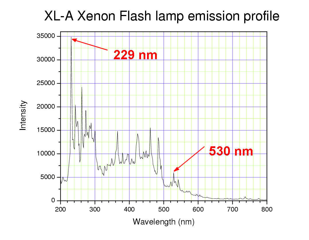
To measure the XENON LAMP EMISSION PROFILE, run an intensity wavelength scan over the dynamic range of the instrument on an empty hole at 6.5 cm. Rotor speed is irrelavent; it is commonly set to 3,000 rpm. You should see a profile similar to the one above, with a peak intensity at 230 nm of at least 15,000 counts. If the intensity is much less than this, clean the lamp, or call for Beckman Services to check the optical system, mirror, PMT, and/or powersupply. If you want to attempt to clean the lamp yourself, and the count is still lower than 15,000 counts, the lamp may need to be aligned. For the XL-A: rotate the lamp in the lamp housing and repeat the intensity scan. Repeat for one full turn, identifying the position that produces the highest intensity. Verify that this is reproducible across every position in the cell.
To measure MONOCHROMATOR FUNCTION, run an intensity wavelength scan over the dynamic range on an empty hole at 5.2 cm, 6.5 cm, and 7.1 cm. If the intensity peaks shift, the monochromator may not be working properly.
The LAMP ALIGHNMENT TEST allows you to measure the response of the machine as a function of radius.
Perform an intensity scan at 280 nm or 230 nm across an empty cell from 5.8 cm to 7.2 cm,
Ensure that the intensity plot does not vary by more than 10$, and that the maximum intensity is in the center.
The maximum intensity at the center indicates that the optical system is properly aligned.
Signal variation of more than 10% can indicate a failing PMT>
For SLIT ASSEMBLY PERFORMANCE testing, you will need to scan a cell with some solution (irrelavant) with 280 nm or 230 nm. Check the overlaid menisci of 40-50 scans. They should form a single sharp peak. If the meniscus shifts back and forth, the slit assembly may need to be serviced.
The slit assembly is a gold foil with laser-etched slits that provides the radial resolution measured by the PMT. This mechanical assembly in the Proteomlab is driven by a servo motor; the Optima AUC uses a digital stepping motor. The stepping motor is much more radially precise at 10 micron resolution. If there is dirt on the slit assembly, it may cause some stepping.
Knowing the CHROMATIC ABBERATION profile of your instrument is especially important for MWL-AUC experiments. Chromatic abberation is a result of each wavelength behaving differently due to the refractive indices of the solution. Once determined, the chromatic abberation profile can be imported into the US-LIMS III database.
Interference Optics Performance Checks
-
Radial Alighment and Counterbalance Calibrations
-
Laser Timing Adjustment (XL-A only)
It is important to attempt to have a well-balanced contrast between both channels of a cell; this is donw by LASER TIMING ADJUSTMENT. This is not necessarily possible for the user with the Optima AUC, as it would need to be programmed into the machine. You can get a Beckman Service rep to ensure that the voltages are set properly, and that the illumination of the camera is well-balanced.